Following the catastrophic fire at Old Tucson Studios in 1995, the author completed a number of on-site visits to Old Tucson to document and survey nearly all surviving component parts on the Reno. These drawings formed the basis of the digital reconstruction of the tender, both in its then-current state and also in its as-built factory appearance (Drawing No. 90). Detailed drawings of actual components and specifications on the engine already appear on Baldwin Drawing No. 20 for an as-built factory appearance. Later upgrades to the Reno, such as the Westinghouse air brake compressor and controls, the Nathan Monitor boiler injector, and the Pyle-National steam dynamo for electrification, were not documented. These drawings ultimately confirmed the original construction specifications according to Drawing No. 20. All together, there are more than 200 individual component drawings and specifications available. For a more detailed cross-referencing to specific components, see The Car-Builder’s Dictionary/Cyclopedia of American Practice, The Railroad Gazette, New York, 1895 Edition – available from Google books.

Separate reports on the original black walnut cab for full reconstruction, the restored US Headlight locomotive headlight, and the replica Baldwin bell fabricated by V&T Enterprises all appear under separate tabs on this website. The available drawing categories and their descriptions are listed below:

A yellow background with some white dots on it
  • Baldwin Order Specifications for the Reno (Transcription)
  • Drawing No. 146 (Nevada Historical Society) – Select Details

1. Firebox vent lever
2. Firebox vent lever, detail 1
3. Firebox vent lever, detail 2
4. Firebox vent lever, detail 3
5. Firebox vent lever, detail 4
6. Steam chest detail
7. Bolt detail

  • Engine:

1. Wheelbases and diameters
2. Builder plate
3. Number plate
4. Number 11 detail
5. Backhead and bolts
6. Platform brace
7. Frame end, step
8. Cab step and column
9. Headlamp bracket, side view
10. Headlamp bracket, front view

  • Brass/Bronze:

1. Bell and clapper
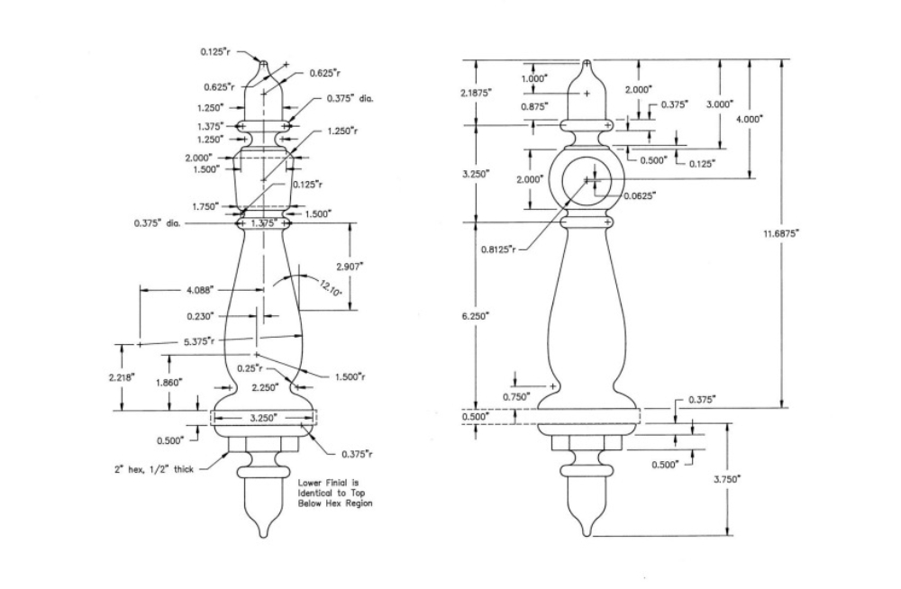
2. Bell stanchion and finial
3. Bell stand, side view
4. Bell stand, top view
5. Bell yoke
6. Bell crank
7. Handrail stanchion and finial
8. Handrail support bar and finial
9. Handrail finial detail
10. Boiler straps
11. Oilers, tulips, and cups
12. Oiler, crosshead
13. Piston cover and finial
14. Oiler tray, backhead in the cab

  • Driver:

1. Driver, frontal and side views
2. Driver crank detail
3. Connecting rod

  • Reno Tender (1995):

1. Side elevation
2. Front and end elevation
3. Top elevation

  • Tank:

1. Tank, side, and top views
2. Tank, front and back views
3. Splicing detail
4. Brackets, front and back
5. Crossbeam, with brake stem support
6. Water valve and flange
7. Water hatch
8. Hook, back tender
9. Lantern catch and bracket, front catch
10. Tender handle

  • Frame:

1. Tender deck, top view
2. Bolt location, deck trim
3. Side sill beam
4. Side sill support
5. Rear corner casting and beams
6. Front corner casting and beams
7. I-beams, end view
8. I-beams, end view
9. I-beams, side view
10. I-beams, top view
11. Truss rod washer casting
12. Center and side center sill hardware

  • Reno Tender (1872):

1. Front draw-head, side view
2. Front draw-head, side view
3. Front draw-head, top view
4. Front draw-head, bottom view
5. Front draw-head, end views
6. Pull-bar and coupling pin
7. Metal flooring and hardware
8. Floor detail with lower beams
9. Inner tank bracing
10. Safety chain hook

  • Truck:

1. Center swing casting, side view
2. Center swing casting, end view
3. Stabilizer, back truck
4. Transverse bars and longitudinal braces
5. Truck frame
6. Truck frame, pedestal detail
7. Crossbeam, back truck
8. Crossbeam, front truck
9. Cross beam strap wedge
10. Spring collar, pin, and hanger
11. Leaf spring
12. Equalizing bar
13. Pedestal
14. Pedestal bar
15. Journal box, side view
16. Journal box, interior detail
17. Journal box, front and back view
18. Journal box, top view
19. Front cover
20. Friction bearing
21. Axle
22. Wheel, back view
23. Wheel, cross-sectional view
24. Blade detail

  • Brake:

1. Brake wheel and stem
2. Ratchet and pawl assembly
3. Brake stem support, end view
4. Brake stem support, side, and top views
5. Brake shoe hanger, side view
6. Brake shoe hanger, projected views
7. Stirrup
8. Brake pad
9. Brake shoe, side view
10. Brake shoe, front and back views
11. Support chain and hardware
12. Brake beam plate
13. Pull-bar and hardware
14. Brake rigging, schematic view

  • Journal Box and Friction Bearing Detail:

1. Assembly cross-section with wheel
2. Journal box and friction bearing

  • Genoa:

1. Boiler running board and nosing detail
2. Tender step casting, detail
3. Tender step casting, top view
4. Tender step casting, front view
5. Tender step casting, side view
6. Tender brake wheel
7. Brass ball end post bracket

A yellow background with stars in it.

For order inquiries, please contact V&T Enterprises at:
[email protected].